Overview
Looking for the GitHub?
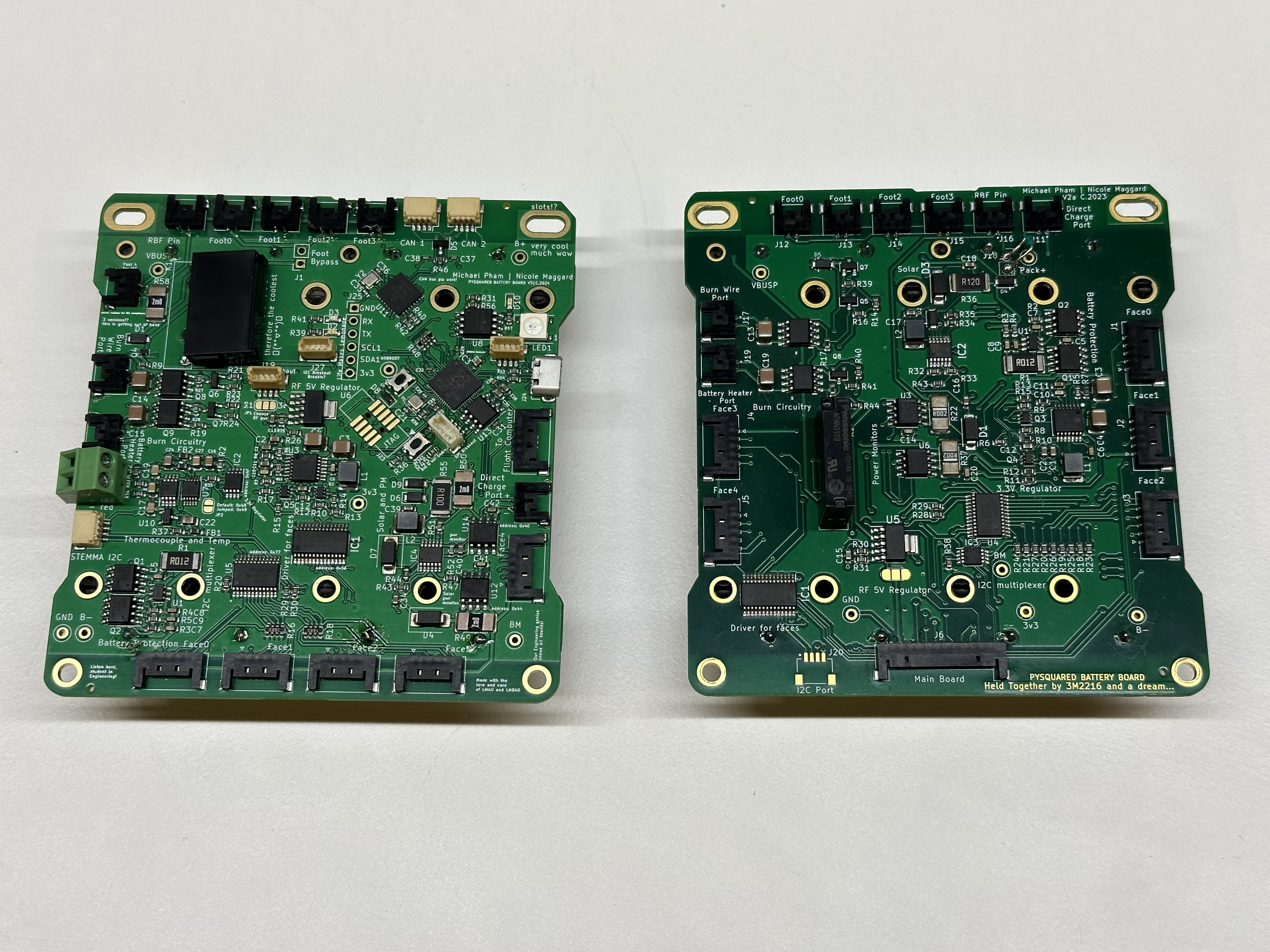
Figure 1: The Battery Board V3 (left) and V2 (right)
The PROVES Kit Battery Board was baselined on the PyCubed battery board, but has since evolved into more of a fully fledged EPS board. This is especially true of V3 and V3a which both host their own RP2040 microcontroller.
Getting Started
Currently there is one officially supported version of the batery board and one in development version:
| Version | Flight Heritage | Description |
|---|---|---|
| V2a | Pleiades - Yearling 2, Pleiades - Squared | This version contains the core functionalities needed for battery and sensor management. |
| V3 | None | This version is a significant overhaul of the battery board, and it implements a RP2040 microcontroller for power management. |
| V3a | None | Removed the multiplexer and LED driver to make way for a switching 5V regulator. |
| V3b | None | More bug fixes over V3a and the first board to be colored red. |
| V3c | None | Changed the thermocouple IC to an SPI chip and added a real time clock. |
Functionalities
graph TD
A[Start] --> B[Boot Sequence]
B --> C{Check Power Mode}
C -->|Critical| D[Critical Power Operations]
C -->|Low| E[Low Power Operations]
C -->|Normal| F[Normal Power Operations]
C -->|Maximum| G[Maximum Power Operations]
D --> C
E --> C
F --> C
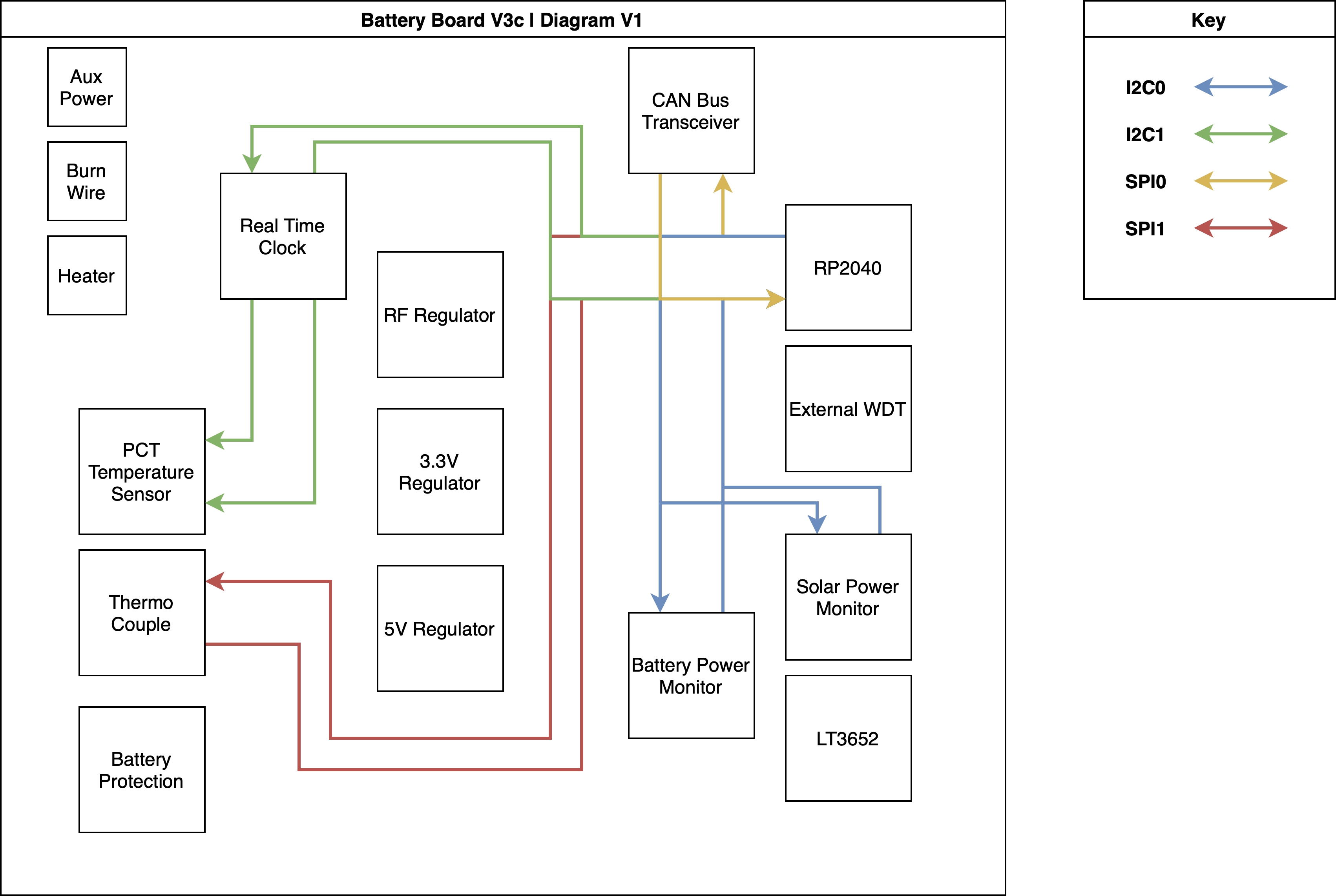
G --> CBlock Diagram
The Inhibit Scheme
One of the most important functions of the battery board is to properly inhibit the satellite and ensure that no electrical power flows while it is inside the deployer pod. For this purpose, there are a set of limit switches that can be attatched to the 2pos headers on the battery board that are thrown open when inside a deployer pod to cut off battery power from the satellite. Usually the requirement is only for two inhibits in series, but we use a 2s2p configuration for redundancy.
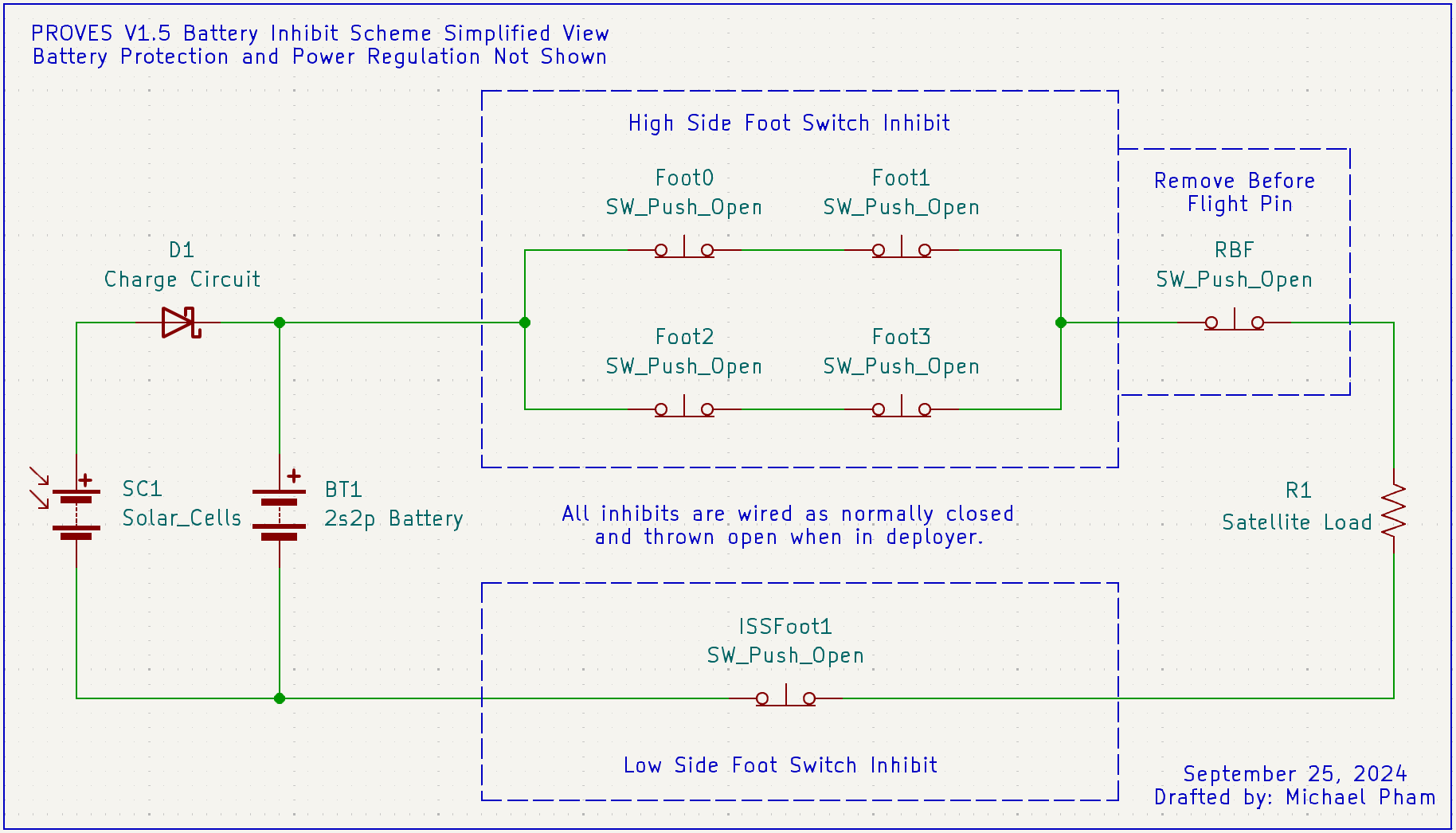
Warning
V2 and earlier battery boards are not ISS compliant as there is no low side inhibit switch that fully isolates the batteries from the rest of the electrical subsystems.
Utilized Parts
The battery board flown on the Pleiades-Yearling and Pleiades-Squared missions. The board serves as an interface with the rest of the satellite. A 12 position picolock is utilized to interface between the Flight Controller and the Battery Board. The board interfaces with 5 solar faces of the satellite using 5 position picolocks. The other 2 position picolocks are used for interfacing with the inhibit scheme, battery heater, burn wire, and direct charging port. The hardware utilized on the module is the following:
LT3652 Solar Charger
This component is used to charge the satellite's batteries using power harvested from solar panels. This part is not a true MPPT solar charger, but it emulates one. There is debate as to whether true MPPT is worth it on small 1U class satellites due to its extra complexity. In the future we will look towards using the microcontroller on the battery board to manage a true MPPT charging curcuit.
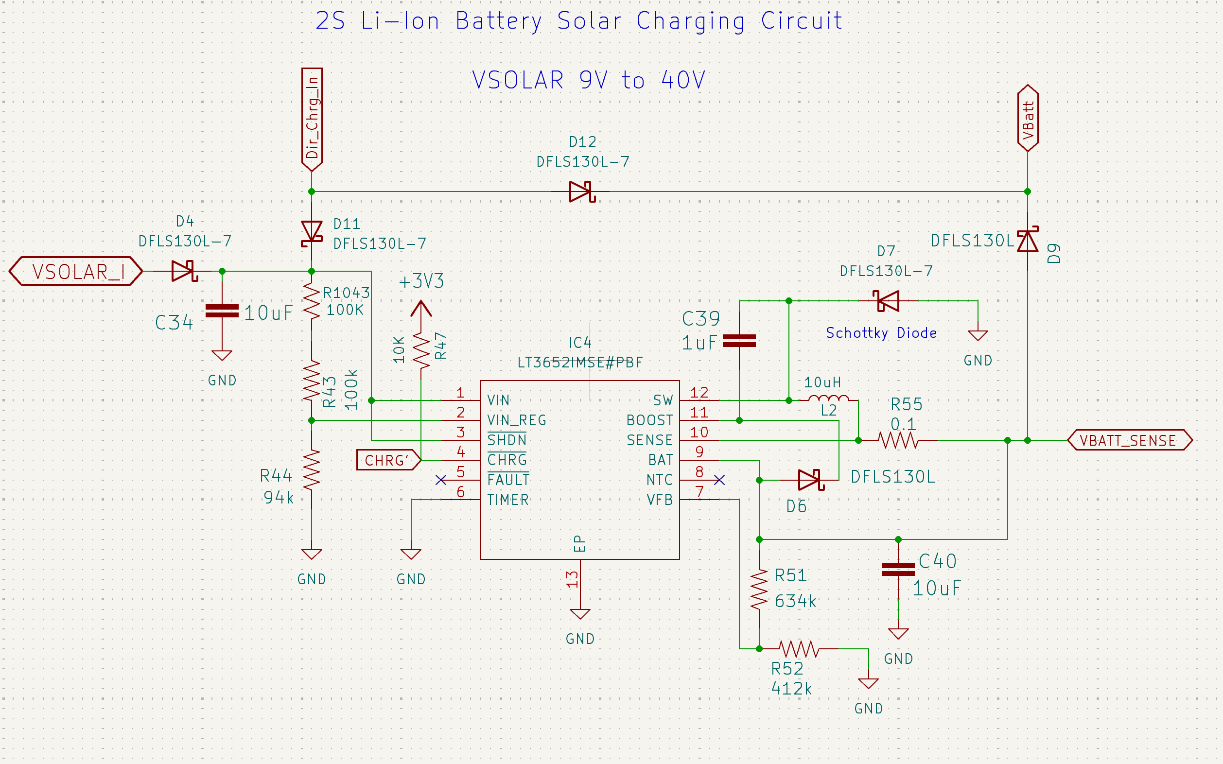
Figure 2: The LT3652 Schematic
PCA9685 LED Driver
The PCA9685 LED Driver controls the power distribution to the solar faces. It enables selective powering of solar face components, facilitating isolation and power-down of specific faces in case of malfunction, thus protecting the system and conserving energy.
Note
In V3 of the battery board this circuit was moved to the Z- panel of the satellite.
TCA9548 I2C Multiplexer
The TCA9548 I2C Multiplexer expands a single I2C bus from the flight computer into multiple channels. This design simplifies the communication with multiple sensors on different solar faces while keeping their addresses identical, enhancing the modularity and scalability of the system. The TCA also appears to provide some level of bus protection, so in the case of an I2C sensor failure the fault is limited to only the face that the sensor is on rather than also interupting all other I2C sensors on the satellite.
Note
In V3 of the battery board this circuit was moved to the Z- panel of the satellite.
TPS54226PWP Switching Voltage Regulator
These two Switching Voltage Regulators are the primary regulator for supplying the microcontroller and sensors onboard the satellite. They creates a stable 3.3V and 5V power supply from the variable battery voltage, and its "One Shot" Regulator Reset feature provides a way to reset the power bus, aiding in system recovery and fault tolerance. This part is borrowed from Max Holliday's PyCubed, and is believed to be slightly more radiation tolerant than other switching regulators due to there being a radiation hardened version in the part family.
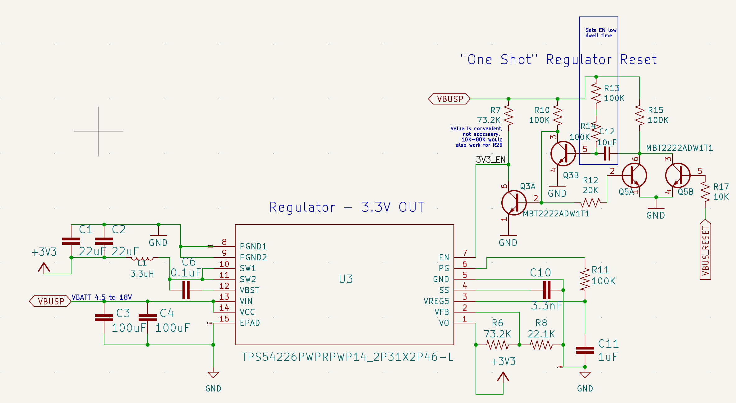
Figure 3: The 3.3V Regulator Schematic
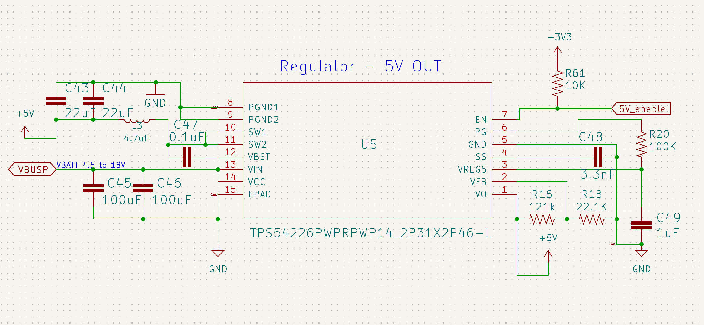
Figure 4: The 5V Switching Regulator Schematic
TPS7A4501 LDO Voltage Regulator
The TPS7A4501 LDO Voltage Regulator is essential for supplying a stable 5V power to critical components like the radio on the flight controller. Although a linear regulator is more inefficient than a switching one, there are significantly lower concerns of noise on the power lines. This is important for ensuring an electrically clean enviroment for the radio to operate in. This part is borrowed from Max Holliday's PyCubed, and is believed to be slightly more radiation tolerant than other switching regulators due to there being a radiation hardened version in the part family.
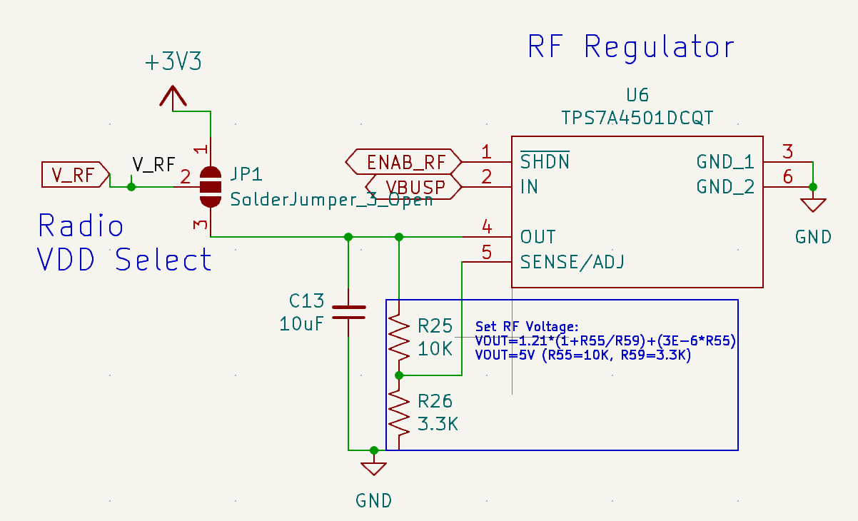
Figure 5: The 5V RF Regulator Schematic
INA219 Power Monitors
These Power Monitors are crucial for real-time tracking of power input from solar cells and power consumption across the system. They provide valuable data for monitoring the health of the electrical power system and for optimizing power usage. These power monitors have extensive flight heritage across many CubeSats.
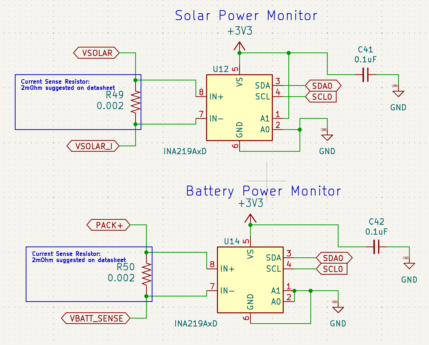
Figure 6: The INA Power Monitors Schematic
PTC2075 Temperature Sensor
The PTC2075 Temperature Sensor provides ambient temperature data from inside the satellite. This information is vital for thermal management, ensuring that the satellite's components operate within their safe temperature ranges.
R5460N208AA
The R5460N208AA plays a protective role by disconnecting the battery in cases of overcharge or overdischarge. This function is critical for battery health and safety, preventing potential damage to the power system. This part is borrowed from Max Holliday's PyCubed.
APAN3109 Relay
The APAN3109 Relay is used to control the flow of current to the battery heater and burn wire MOSFETs. It is an essential component for managing the deployment mechanisms and thermal systems of the satellite.
The Burn Wire Circuit
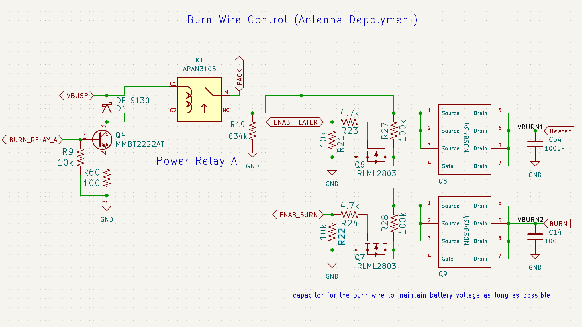
Figure 6: The Burnwire and Heater Schematic
In order to hold the antennas in a stowed position during launch we tie them off with a fishing line and use a nichrome wire to burn through that fishing line when it is time to deploy. This circuit is borrowed from Max Holliday's PyCubed. The NDS8434 MOSFETS are fed battery voltage to their sources when the APAN relay is closed and the voltage that they transmit through to the burnwire is modulated using a PWM signal from the uController fed into the gate.
Burnwire Burn Through
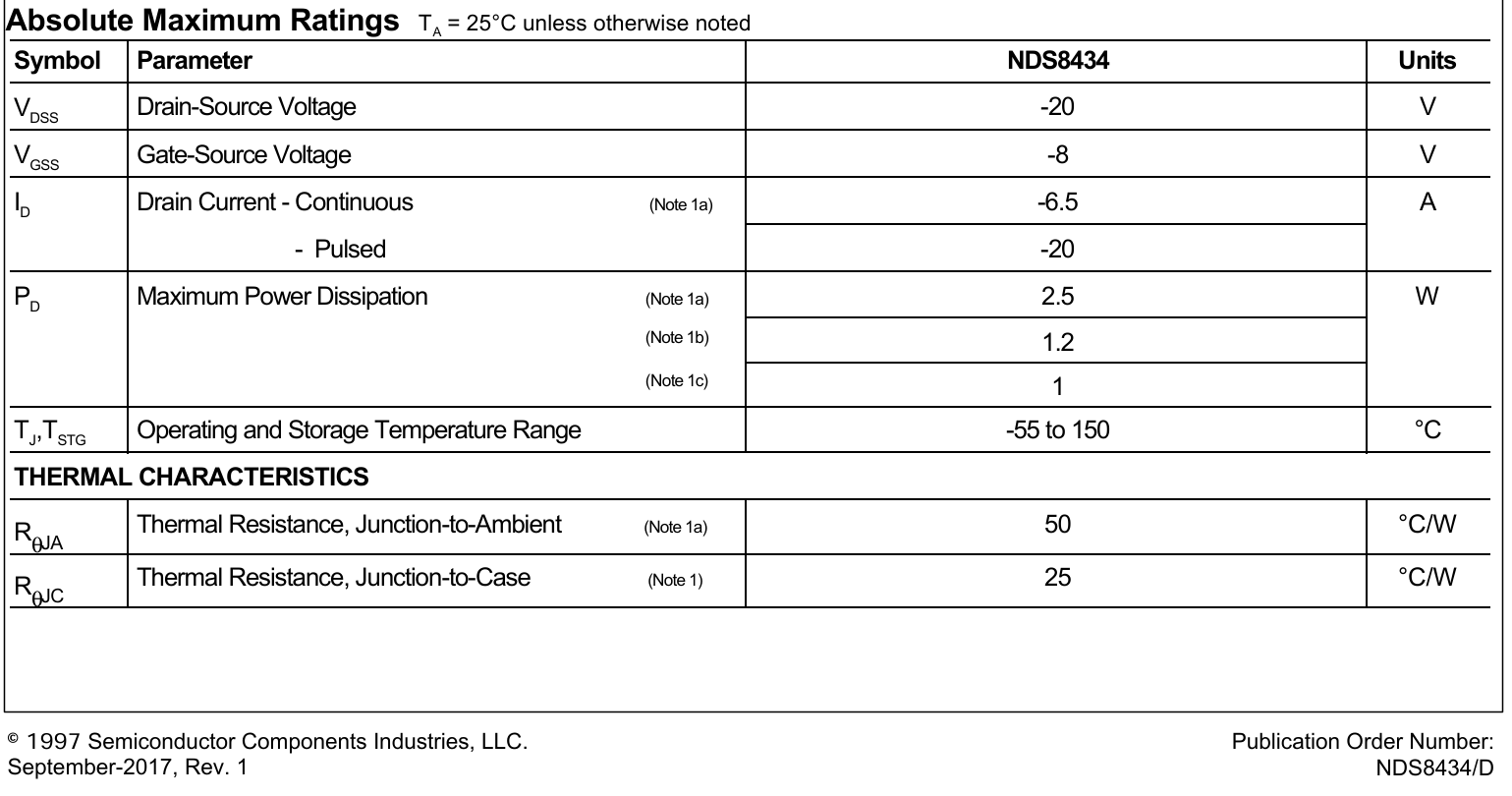
If the power that flows through the NDS MOSFETs is too high the circuit will "burn through" and cause a short circuit that will trigger an overcurrent event any time battery voltage is introduced to the circuit. The attatched table from the ON Semi datasheet shows that although the max drain current is 6.5A, the MOSFET can only disapate between 1W and 2.5W.
Right now, to consistently burn the burn wire we need to use a duty cycle of around 0.22, which (assuming a wire resistance of ~0.3 Ohms and battery voltage of 8.0V) correlates to sending 8.53W through the circuit! Way higher than what is safe.
We are currently looking at changing this entire circuit out for the V4 Battery Board.
Known Issues
- Although the R5460N208AA is supposed to auto-release in the case of a battery protection event, it does not appear to actually do this. If you find that the satellite is not delivering power because of a battery protection event that has now been cleared, you can reset the protection circuit by "jump starting" the satellite by applying a voltage higher than the current voltage of the batteries. On-orbit these jump starts should be automatically applied by the solar charger, if they are needed.
- The MOSFETS in the Burn Wire and Battery Heater Circuits have much lower power carrying capacity than they should for their application. This presents a relatively high risk of "burning through" the two circuits if they get too hot, especially in vacuum.
Troubleshooting
Schematics
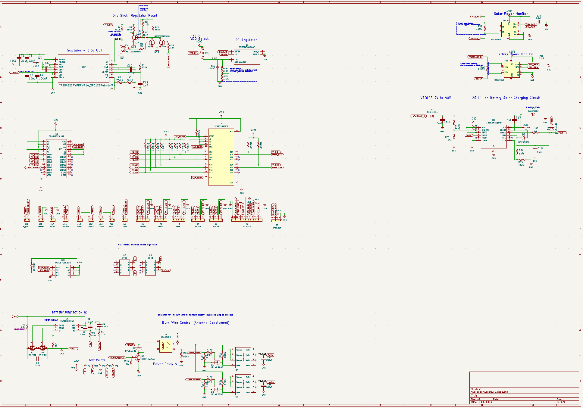
The V2 Battery Board Schematic
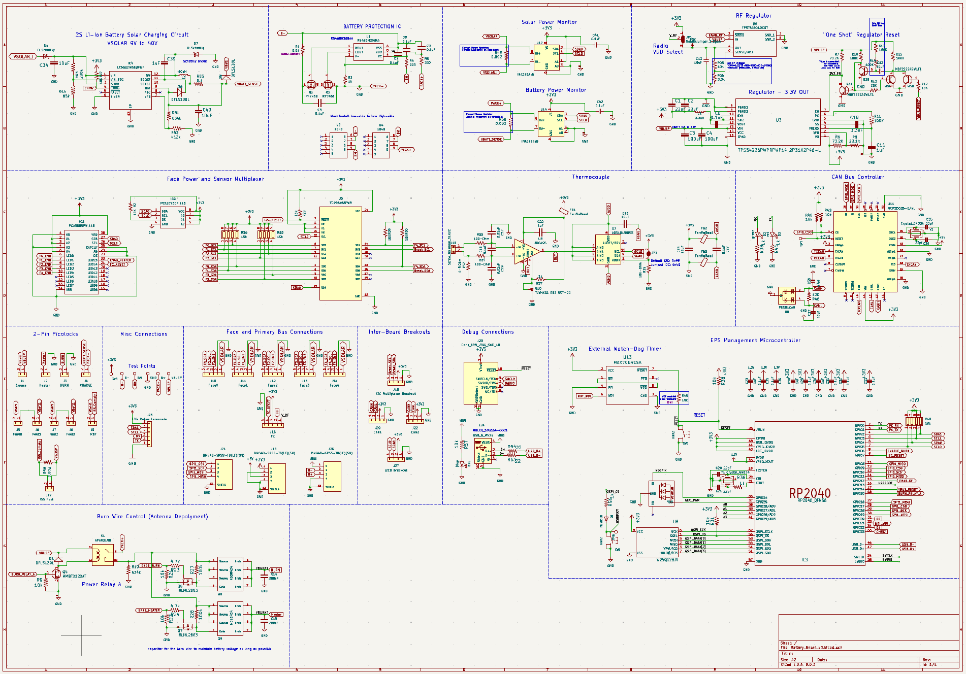
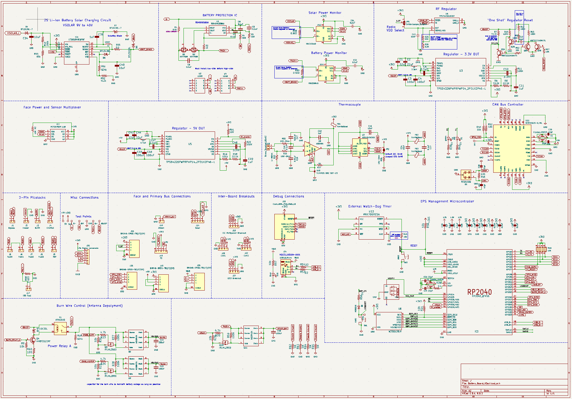
The V3 Battery Board Schematic
The V3a Battery Board Schematic
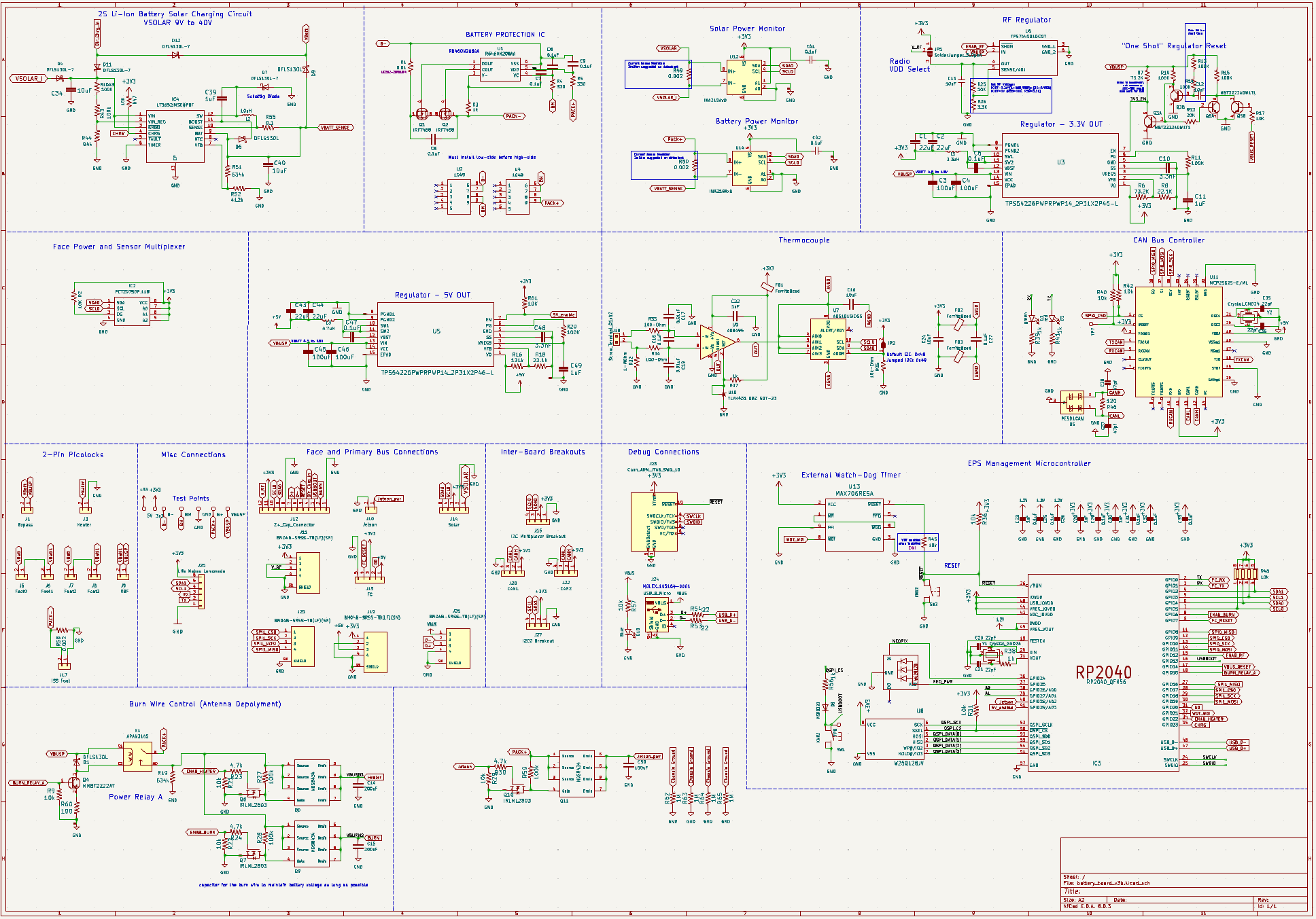
The V3b Battery Board Schematic
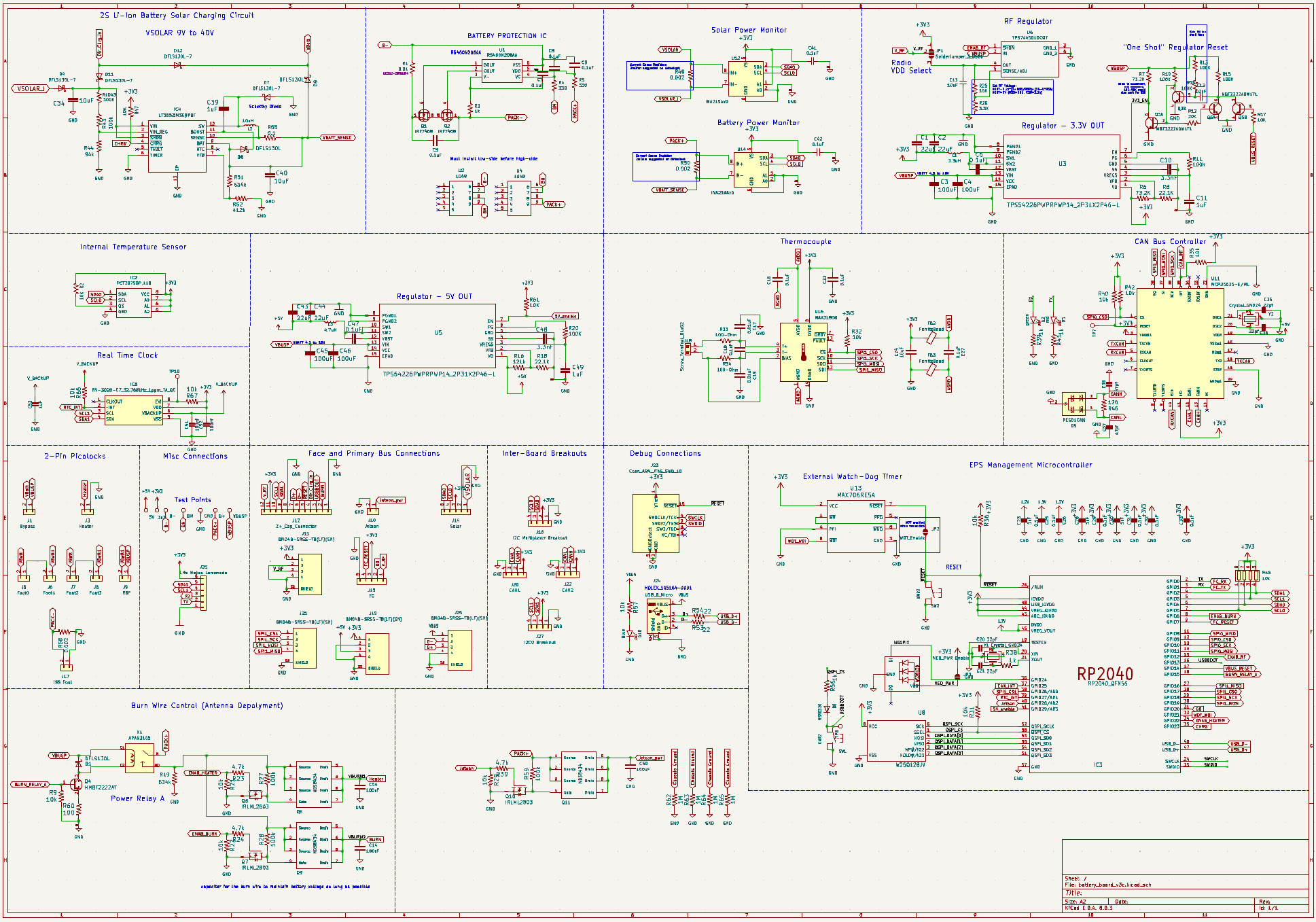
The V3c Battery Board Schematic