Chapter 6: Structure Pre-Integration
Cataloging Parts
#### The Structure
Warning
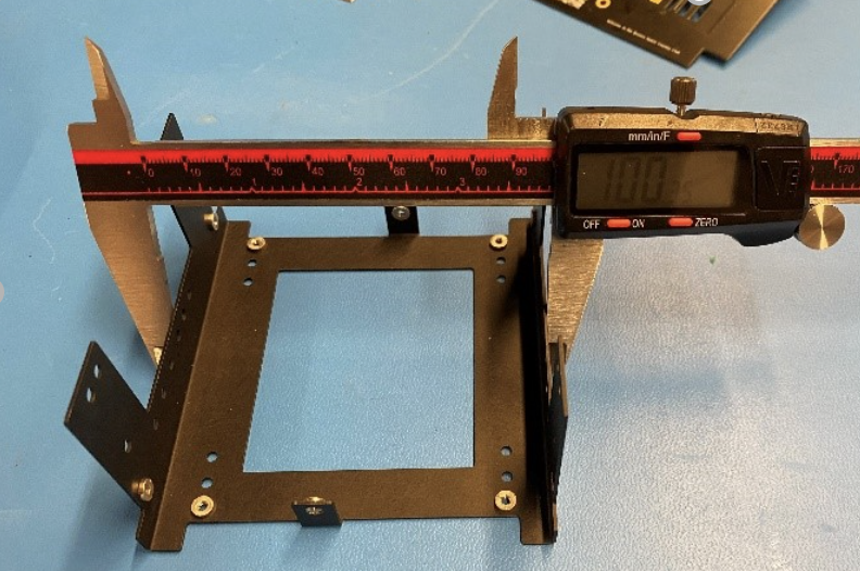
When measuring it is important to not bend the U-shape inwards. Take the measurement as close to the “closed” side of the U as possible.
1. Measure the dimensions of each half of the anodized Main “U” structure and label them. Use calipers to measure the width of each of the two sheet metal halves.
Figure 6.1: How to make measurements of Main “U” structure.
Note
These additional measurements are useful for verifying that your satellite will fit inside a launch vehicle pod after integration is complete and to ensure no damage has occurred during shipping.
Figure 6.2: Sample measurements of the U structure
Tip
It is important to record and identify which "U" structure halves are most optimal for flight if you have more than two "U" structure halves The structures should come in at about 99.77mm nominally, but they will vary depending on the bends and the anodizing.
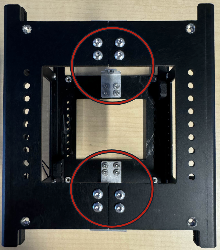
2. Checking out the PEM-Nuts The structure and brackets all contain PEM-Nuts.
Figure 6.3: Locations of PEM-Nuts
Note
The Jig is needed in order to ensure the satellite is squared up enough to fit into its deployment mechanism.
3. Accessing the Jig STL File Access the GitHub Documentation repository where an STL file can be obtained and printed for the jig.
4. Repeat steps 1 through 3 for each solar board.