Chapter 4: Flight Controller Assembly
- Install NeoPixel and VL6180 LiDAR
a. Apply Low-Temperature Solder Paste to both part pads as seen in Figure 4.1.
Figure 4.1: Application of Low Temp Solder Paste
b. Place components in proper orientation as seen in figures 4.2 and 4.3.
c. Place Standoffs in reflow oven (this is to avoid letting the board touch the oven tray). d. Place board on standoffs and set the oven to 185C or temperature slightly above solder paste’s recommended temperature.
Note
The NeoPixel does not need to be populated but can be utilized by the Flight Controller to show the status of the system.
- Hand Solder the Micro USB port a. Pre-tin the pads of the Micro USB port as seen in Figure 4.4.
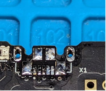
Figure 4.4: Pre-tinned pads
b. Insert USB onto Footprint and flip board over as seen in Figure 4.5.
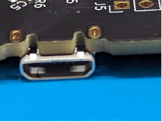
Figure 4.5: USB Orientation upside down
c. Solder through hole pins of USB to ensure structural stability of connector as seen in Figure 4.6.
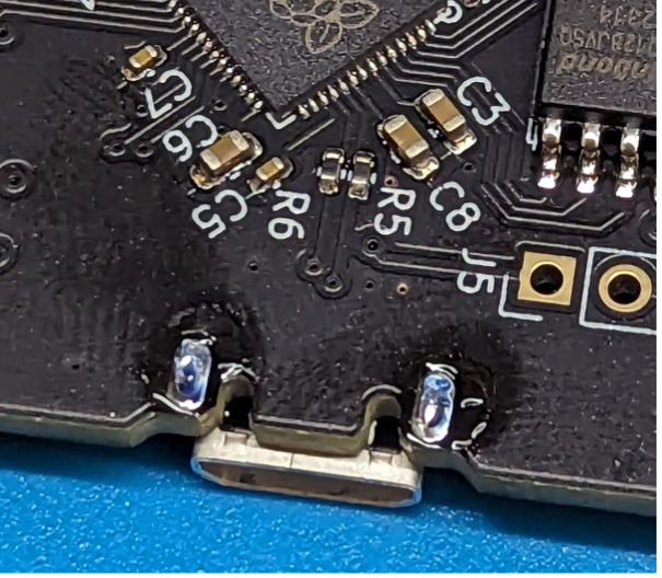
Figure 4.6: Soldered USB Structural Supports
d. Flip Board over and apply hot air to the connector while holding the connector down with a pair of tweezers as seen in Figure 4.7.
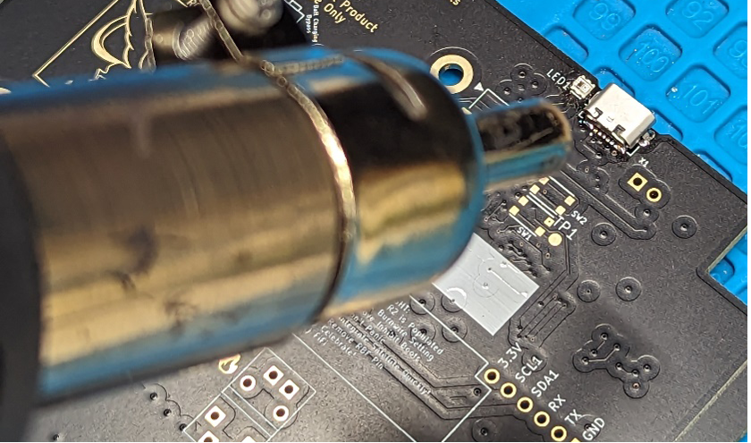
Figure 4.7: Applying Hot Air
e. After removing the heat the connector should be adequately Soldered to the Board and should appear as in Figure 4.8.
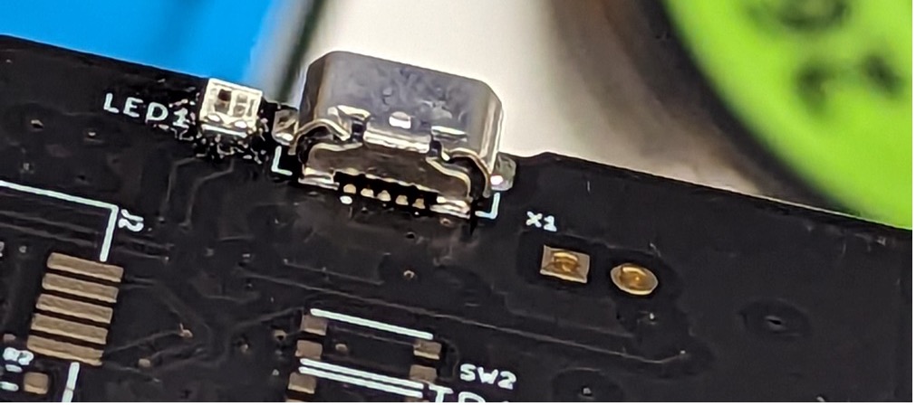
Figure 4.8: Final Appearance
- Loading the Firmware onto the board
Note
The Firmware and Flight Software can be obtained on the GitHub: www.github.com/proveskit
a. After soldering the USB connector onto the board the flight controller can be plugged into the computer and power should enter the system by jumping the pins of J? as seen in Figure 4.9.
Figure 4.9: J? Pins
b. A Blue LED should then turn on as seen in Figure 4.10 and the file system RP1-RP2 should be detected as seen in Figure 4.11.
Figure 4.10: The Blue LED
Figure 4.11: RP1-RP2 in the File System
c. Drag and Drop a UF2 file into the file system. Several options for Firmware are available.
d. After dropping the firmware into the file system a new file system should load with the name “Pysquared” as seen in Figure 4.12. e. Load Flight Software from the GitHub Repository onto the File system allowing all files to be replaced. f. Open a new session on a terminal software that can read the output from the flight controller. The output should look similar to that seen in Figure 4.13.
Note
If the output is not like what is seen in Figure 4.13 try reloading the software by pressing ctrl+C and then ctrl+D.
-
Hand Solder the Balun a. Follow the silkscreen pattern on the board to place the component in the correct position. The dot should be facing outwards from the PCB and towards the USB port side of the board as seen in Figure 4.14. b. Solder the Balun to the board. Using Tweezers can help hold the balun down while applying heat.
-
Install the Hope RF Radio module a. Use Kapton tape to cover the smaller set of pads that would sit under the Radio Module as seen in Figure 4.15.
Figure 4.15: Radio Pads
b. Hand solder radio into place and it should appear like either Figure 4.16 or 4.17.
c. If using the smaller radio module then a Jumper wire should be soldered to the pads as seen in Figure 4.18. d. If using the smaller radio module the following cable seen in Figure 4.19 should be removed from the cable assembly and that side specifically should be inserted into the flight controller as seen in Figure 4.20.
Warning
If using the smaller radio module it is imperative that the user does NOT plug in the 12 position Molex Picolock connector UNTIL following the next step.
-
Solder two position Pico-Lock headers a. Follow the silkscreen pattern on the board to place the two headers in the correct positions/orientations and solder them into place. The connectors should appear as they do in Figure 4.21.
Figure 4.21: Pico-Lock Headers Placement
-
Solder the Burn Wire to the Flight Controller Board a. Insert some Nichrome wire into the hole seen in Figure 4.22.
Figure 4.22: Inserting Nichrome Wire
b. Bend the wire on the opposite side of the board and insert into adjacent hole and pull tight as seen in Figure 4.23.
Figure 4.23: Wire Bending and Insertion
c. Create a large loop on the top side of the board and insert the wire back into the board as seen in Figure 4.24.
Figure 4.24: Creating Wire Loop
d. Bend the wire into the adjacent hole and pull tight as seen in Figure 4.25.
Figure 4.25: Final Wire Bending
e. Solder the Wire at all Pads on the top and bottom of the board. Also snip ends of wires so that it appears like Figure 4.26.
Figure 4.26: Soldering and Snipping Ends of Wire
f. Press down on the center of the wire loop on the top side of the board as seen in Figure 4.27.
Figure 4.27: Pressing Down on Wire Loop