Chapter 2: Feet and Heater Assembly
In this chapter the user will learn the steps to assemble a foot switch. A minimum of two will be needed for any space application, but four switches would be recommended to increase redundancy.
Warning
Before continuing: it is important to note that gloves should worn when soldering and it should be done in a well-ventilated area to avoid the harmful fumes.
Make 4-6 Jumped 2 Position Pico-Lock Cable Assemblies
Note
300mm 5 position Pico-Lock cable assemblies have been included in the kit as well as 2 position connectors. The 100mm assemblies will be used for connecting the solar boards to the EPS, and the 300mm assemblies will be used to create all the needed 2 position Pico-Lock assemblies.
1. The first step will require taking a cable out of the 300mm 5 position assembly. To start, take the needle nose tweezers and lift the locking mechanism as seen in Figure 2.1 and pull the cable from each connector housing.
Figure 2.1:
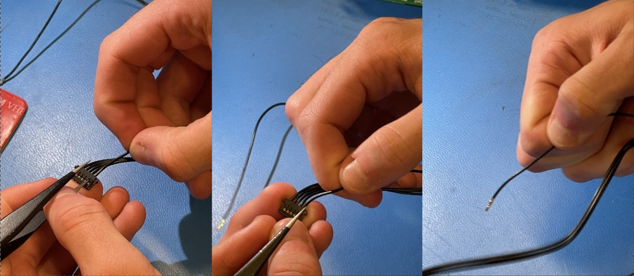
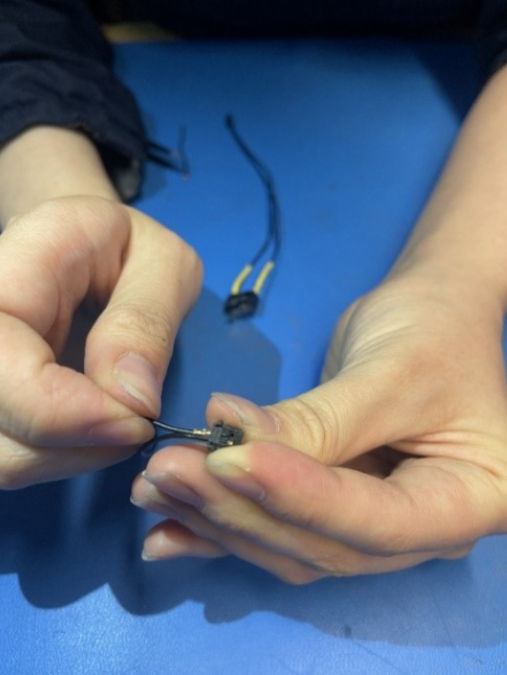
2. Take the freed cable and insert both ends into one 2 position connector housing as seen in Figure 2.2
Figure 2.2:
Note
The steps are similar for creating the non-jumped cables required for the burn wire and direct charging ports. The primary difference is that two cables will be required as well as 2 connector housings.
Solder the Jumped Pico-Lock Assemblies to the switches
1. Take jumped assembly and cut in half as seen in Figure 2.3
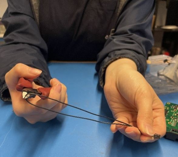
Figure 2.3
2. Strip ends of assembly wires 3. Slide heat shrink tubing down each wire 4. Wrap wires around leads 1 and 3 respectively as seen in Figure 2.4 Figure 2.4
5. Solder wires to switch leads
6. Move heat shrink tubing up and use hot air to shrink tubing around switch leads
7. Repeat these steps to create 2-4 foot switches and 1 RBF switch
Solder the Battery Heater Assembly
1. Take jumped assembly and cut in half as seen in Figure 2.4 2. Strip ends of assembly wires 3. Slide heat shrink tubing down each wire 4. Strip ends of battery heater leads 5. Wrap wires around leads as seen in Figure 2.5
Figure 2.5
 6. Solder wires to heater leads
7. Move heat shrink tubing up and use hot air to shrink tubing around heater leads
6. Solder wires to heater leads
7. Move heat shrink tubing up and use hot air to shrink tubing around heater leads
Create Foot Switch Assemblies
1. Insert the M2x20 bolts into the holes of the non-embedded feet as seen in Figure 2.6
Figure 2.6
 2. With the bolt inserted, apply some Loctite to the bolt on the opposite end
3. Holding the bolt in place with a Philips head screwdriver, insert the M2 lock nut into the opposite end of the foot and tighten the nut partially without allowing the bolt to go completely through the lock nut as seen in Figures 2.7 and 2.8
2. With the bolt inserted, apply some Loctite to the bolt on the opposite end
3. Holding the bolt in place with a Philips head screwdriver, insert the M2 lock nut into the opposite end of the foot and tighten the nut partially without allowing the bolt to go completely through the lock nut as seen in Figures 2.7 and 2.8
Figure 2.7 and Figure 2.8*
4. Prepare a small amount of space rated glue 5. Apply the glue to the inside of the foot on the areas shown in Figure 2.9
Figure 2.9
6. Insert the switch into the foot as seen in Figure 2.10 Figure 2.10 7. Repeat steps for all foot switches 8. Insert all foot switch assemblies into the reflow oven and bake at 185C this will help cure the glue faster. 9. Let rest for an additional hourCreate RBF Switch assembly
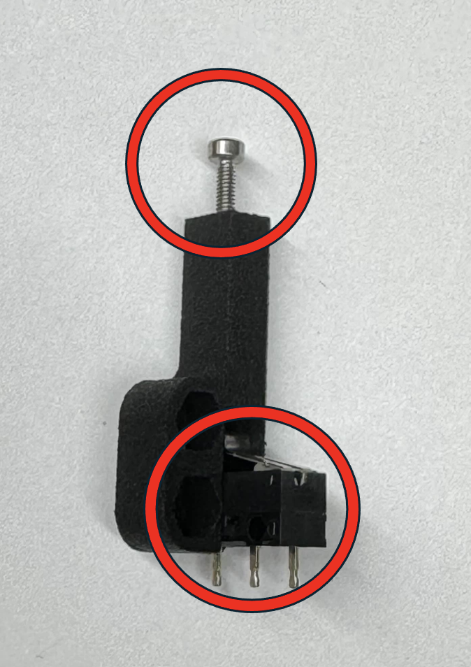
1. Insert RBF switch into holder as seen in Figure 2.11
Figure 2.11
2. Insert and fasten M2.5x8 or M2.5x10 bolts into the 3d printed side. The assembly can be seen in Figure 2.12Figure 2.12